To ensure the safe operation of the device it is recommended to read this user manual completely before starting to use the device.

  • RF Frequency: 433MHz
  • Power supply: 12-24Vdc / 12Vac
  • Output: 1 COM relay contact
  • Section of the power cables: 1,5mm2
  • Maximum section in load circuit: 2,5mm2
  • Dimensions: 50x50x25mm
  • Maximum loads:
    • Resistive loads (light, bulbs, halogen lamps…): 12A
    • Inductive loads: 3.5A/350W/cosj=0,4.

This Enabler with one relay switched contact and powered with low voltage, is designed to activate elements such as motored doors, one-light circuit, a warning, the doorbell, etc.

BJ Enabler 1R-LV

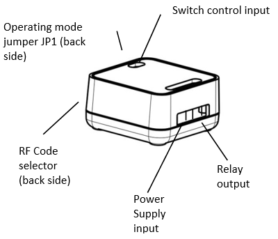
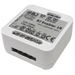
Fig. 1. BJ Enabler 1R-LV.


You can activate the Enabler remotely using any of the BJ System’s remote controllers or directly via special switches.

Pre-installation 


For correct installation, the Enabler must be fitted in a sealed box that provides sufficient space, absence of dust and humidity and isolation from direct contact with people.

To install the Enabler you must carry the Enabler’s power cable, load cable and switch’s cable to the box where it will be installed.


Installation


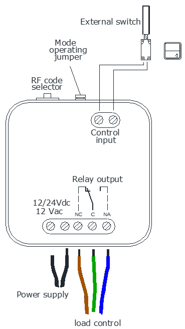
For a proper installation of the device see figure 2:

CAUTION!  Electrical installation may only be carried out by a qualified electrician!

Do not make any unauthorized alterations or modifications to the unit.

The relay contact is only suitable for low voltage power supply (12-24 V dc/ 12V ac)

Observe the manufacturer’s instructions for the device to be operated.

CAUTION!  An error in the connections may cause serious damage to the device or the installation, or harm to the operator.

IMPORTANT:  See the device technical data to check the type and maximum loads that can be connected to the Enabler. Power cables must be stripped a distance of 6mm.

Once the Enabler’s connections are made and before connecting the device to the power supply, you must choose the position on the “RF code selector” (see figure 1).

To control the load via an alternative access switch, connect the two cables of the switch to the Control input.

This Enabler is designed for switching devices in two selectable operating modes:

  • Mode 1: “ON/OFF” The relay is triggered and deactivates alternatively with each signal received.
  • Mode 2: “Pulse” The relay is triggered during 1 second when receiving a signal.

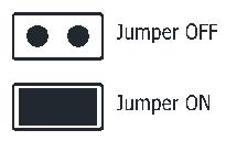
The operating modes can be configured by means of the jumper JP1 (see figure)

  • JP1 OFF (jumper disconnected): Pulse mode
  • JP1 ON (jumper connected): ON/OFF mode

Use the RF code selector to select the code that will activate the Enabler. The code selector allows up to 10 positions. See in the table below the code assigned to each position:
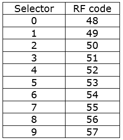
Table 1.


IMPORTANT: To change the code in the selector, disconnect the Enabler from the power supply, wait five seconds and reconnect the circuit.

To use the Enabler:

  1. The device must be installed in accordance with the installation instructions (see section 4).
  2. Program the RF code in the BJ System’s remote controller based on the position of the selector and the corresponding value in Table 1. See the controller’s user guide to learn how to program the RF codes.
  3. The Enabler will activate/deactivate the load depending on the mode selected (see section 5) when the programmed button in the controller is pressed.
  4. If external switches have been installed, the load can be turned on and off using these elements.
  • Enabling multiple receivers at once: To enable multiple receivers plugged in different locations and that these are activated at once, simply adjust the “RF code selector” in the same position on all receivers.
  • Activation of different receivers: To enable multiple receivers, so that each one is activated with a different action in the controller, simply adjust the “RF code selector” in a different position on each receiver.

The Enabler can be cleaned using a damp soft cloth. Always carry this operation out with the Enabler disconnected.

In the event of a fault in the Enabler, do not handle it and contact your distributor.

Waste electrical products should not be disposed of with household waste!

Dispose of the waste product via a collection point for electronic scrap or via your specialist dealer.

Put the packaging material into the recycling bins for cardboard, paper and plastics.

Within the statutory warranty period we undertake to rectify free of charge by repair or replacement any product defects arising from material or production faults.

Any unauthorized tampering with, or modifications to the product will annul this warranty.

This product complies with the essential requirements of the Directives 2004/108/EC and 2006/95/CEE.

You can consult the declaration of conformity at: BJ-232_conformity.pdf

If, despite of correct handling, faults or malfunctions occur or if the product was damaged, please contact us at the address below:

BJ Adaptaciones
C/ Mare de Déu del Coll, 70, Bajos
08023 Barcelona, Spain
Phone: +34 93 285 04 37
Fax: +34 93 553 56 34
e-Mail: info@bjliveat.com
www.bjliveat.com